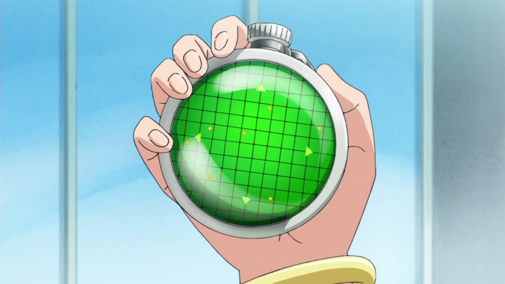

Inspiration
If you want a real life Dragon Radar , there are a small amount of toys to choose from.
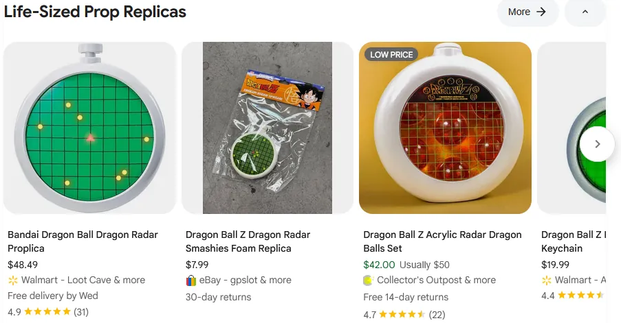
None of those can really function as the radar from the anime. The maker in me wanted to change that.
There were some bumps along the way, but the first revision turned out alright. I’ll disclose all those bumps, and the eventual working prototype, in this dev1log.
Prototyping
CircutPython
A Dragon Radar requires a circular screen. In recent years, these have become more available to the hobbyist maker. There are lots on Alibaba and Aliexpress, but Adafruit has 4" and 2.8" varieties that are not only well documented but have a complementary dev board: the ESP32-S3 Qualia.
This is where I began prototyping and quickly hit an impasse. Adafruit prioritizes CircuitPython and I couldn’t get the CIRCUITPY drive to show up on my Linux machine. I bumbled around factory reset and bootloader repair documentation only for flashing to work first try after connecting the Qualia to a Windows machine. Not sure why.
Once I flashed the newest CircuitPython onto the Qualia, it showed up on my Linux machine. Maybe it’s on old bug that’s hence been repaired.
Display Driver
Once CircuitPython worked, driving the display was easy using Adafruit’s provided example code.
from displayio import release_displays
release_displays()

import displayio
import busio
import board
import dotclockframebuffer
from framebufferio import FramebufferDisplay

init_sequence_hd40015c40 = bytes((
    ...
    """obnoxiously long init code, scroll to the end for the repo containing the full code"""
    ...
))

tft_pins = dict(board.TFT_PINS)

tft_timings = {
    "frequency": 16000000,
    "width": 720,
    "height": 720,

    "hsync_pulse_width": 2,
    "hsync_back_porch": 44,
    "hsync_front_porch": 46,
    "hsync_idle_low": False,

    "vsync_pulse_width": 16,
    "vsync_back_porch": 16,
    "vsync_front_porch": 50,
    "vsync_idle_low": False,

    "pclk_active_high": True,
    "pclk_idle_high": False,
    "de_idle_high": False,
}

board.I2C().deinit()
i2c = busio.I2C(board.SCL, board.SDA)
tft_io_expander = dict(board.TFT_IO_EXPANDER)
#tft_io_expander['i2c_address'] = 0x38 # uncomment for rev B
dotclockframebuffer.ioexpander_send_init_sequence(i2c, init_sequence_hd40015c40, **tft_io_expander)
i2c.deinit()

bitmap = displayio.OnDiskBitmap("/round-display-ruler-720p.bmp") # place this file in the root of CIRCUITPY

fb = dotclockframebuffer.DotClockFramebuffer(**tft_pins, **tft_timings)
display = FramebufferDisplay(fb, auto_refresh=False)

# Create a TileGrid to hold the bitmap
tile_grid = displayio.TileGrid(bitmap, pixel_shader=bitmap.pixel_shader)

# Center the image
tile_grid.x -= (bitmap.width - display.width) // 2
tile_grid.y -= (bitmap.height - display.height) // 2

# Create a Group to hold the TileGrid
group = displayio.Group()

# Add the TileGrid to the Group
group.append(tile_grid)

# Add the Group to the Display
display.root_group = group

display.auto_refresh = True

# Loop forever so you can enjoy your image
while True:
    pass
I should note that I ran into an error when trying to program the board.
OSError: [Errno 5] Input/output error
This prevented me from updating the code. Other people have had this problem too apparently. I still don’t know the root cause, but the work around I used on Linux was:
sudo cp code.py /media/<username>/CIRCUITPY/code.py
Sound
This was the first hiccup. This demo of the Adafruit team playing Star Trek on the Qualia made me confident that the board could be the base for a Dragon Radar.
Those familiar with the Dragon Ball series will know the radar makes this sound:
My implementation didn’t sound as good. I bought a breakout board for the same I2S2 chip used in the above demo, the MAX98357, and connected it to the Qualia board.
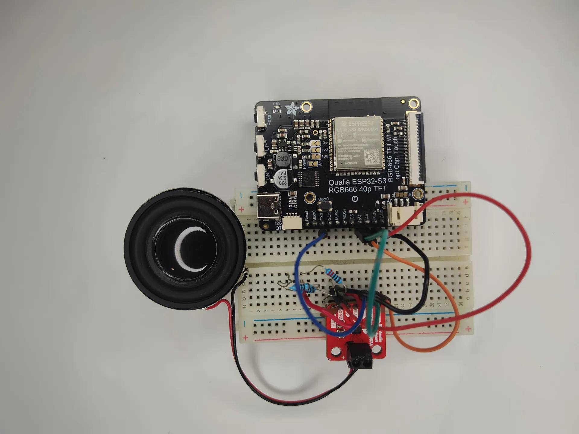
The first audio file in this section sounded like this played through my prototype hardware (put the volume down):
The crackling sound is not your speakers. That’s actually what was coming out of my breadboard set up. I used, what I believe to be, the same speakers as the one Adafruit demoed as well as a 8 ohm variant, but that didn’t change anything. Modifying the gain or the stereo/L/R output of the amp didn’t fix the issue either.
I doubt the code is suspect but here it is in case you can find something wrong with it.
# SPDX-FileCopyrightText: 2018 Kattni Rembor for Adafruit Industries
#
# SPDX-License-Identifier: MIT

import audiocore
import board
import audiobusio

wave_file = open("beep.wav", "rb")  # must be CIRCUITPY filesystem
wave = audiocore.WaveFile(wave_file)

# For Feather M0 Express, ItsyBitsy M0 Express, Metro M0 Express
# audio = audiobusio.I2SOut(board.D1, board.D0, board.D9)
# For Feather M4 Express
# audio = audiobusio.I2SOut(board.D1, board.D10, board.D11)
# For Metro M4 Express
# audio = audiobusio.I2SOut(board.D3, board.D9, board.D8)
i2s_bit_pin = board.A1
i2s_word_pin = board.A0
i2s_data_pin = board.TX
audio = audiobusio.I2SOut(i2s_bit_pin, i2s_word_pin, i2s_data_pin)

while True:
    audio.play(wave)
    while audio.playing:
        pass
I don’t have a lot of familiarity with I2S or sound circuits in general. Since something played I suspect the haphazard wiring is the culprit. Hopefully a PCB3 will fix the issue. So I pressed on to electrical-mechanical design.
Enclosure Design
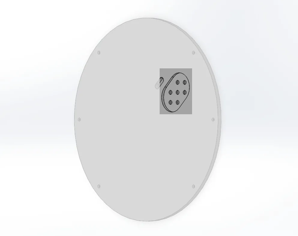
Display Mounting
Given the unique shape of the Dragon Radar, I started with designing a 3D model. In the anime, it took on slightly different looks.
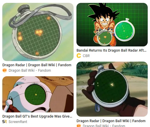
There are two constraints mandatory to match the anime:
- The display has to be at the center of the enclosure
- The activation button must be at the top of the enclosure, aligned with the vertical symmetrical axis
These two constraints seem simple, but forced my hand during mechanical design.
I decided to use the 4" display, HD40015C40, since I figured a display that was too big was better than one that was too small. I didn’t have the display in hand yet when designing the enclosure so I had to go off its datasheet.
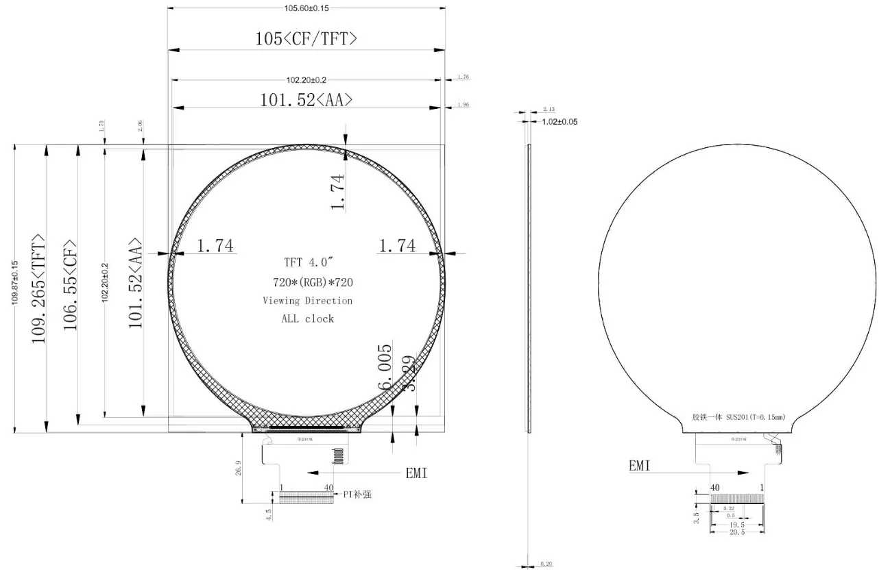
It was in Chinglish and honestly frustrating to interpret. What I could figure, though, was the visible pixels on the screen are not centered in the display assembly. In fact, the center of the display assembly’s bounding box and the center of the active pixel area are offset by 2.44 mm.
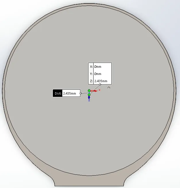
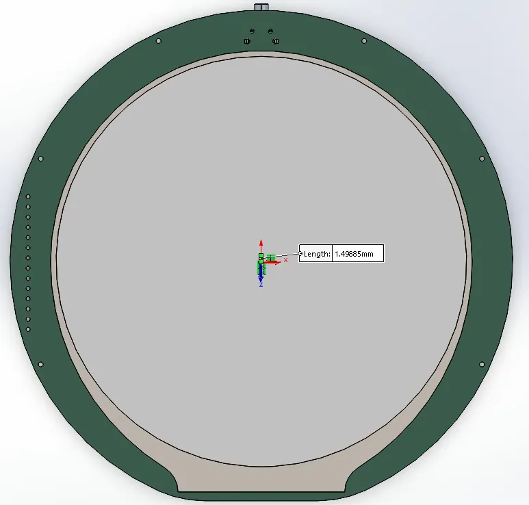
I was able to reduce the offset to 1.5 mm in the opposite direction with the activation button’s placement. I used a THT4 switch for mechanical strength, which forced the PCB to be bigger than the display so the switch’s leads didn’t cause a collision.
To keep the screen centered in the end product, I had to put a sizable bevel around the enclosure’s edges.
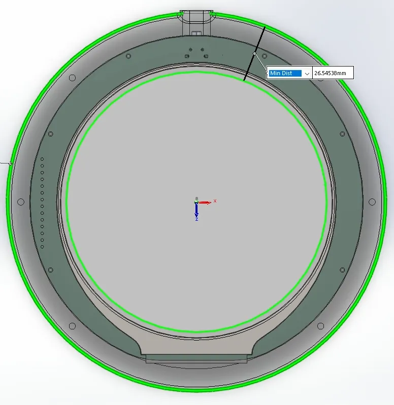
This is close enough to the anime. Finishing the mechanical design for the user input changed things though.
Activation Button
The button to turn the device on and off is actually an assembly of a shaft and cap. There’s heat-set inserts in each part and they’re assembled together with a set-screw.
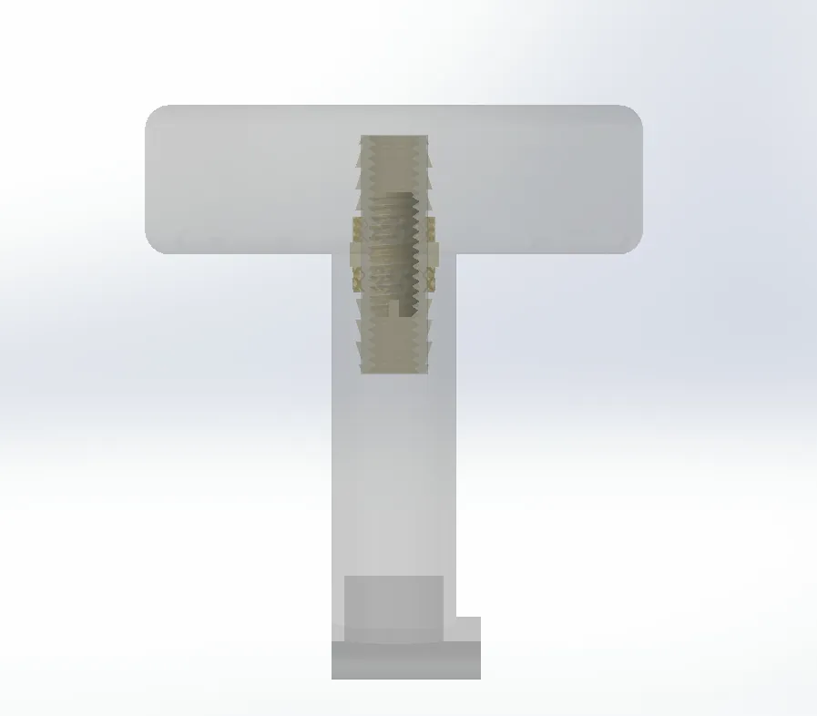
This is where the beveled edges on the enclosure became a problem. Bear with me because this dependency tree is a little convoluted. Because the switch is on the same PCB as the display, and switches are only available at certain heights, and the activation button must be on the same axis as the switch’s actuator: the shaft for the activation button can’t sit on the top of the enclosure like in the anime.
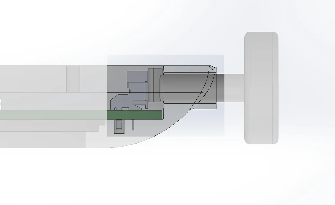
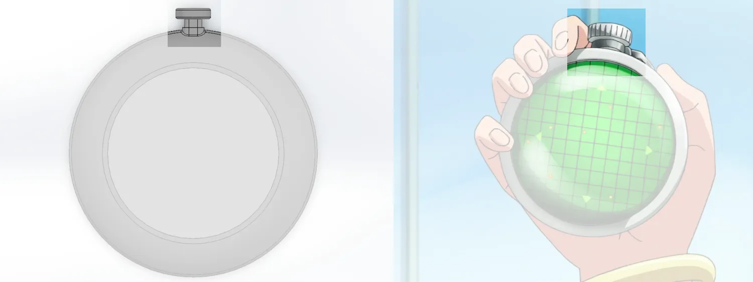
This is fine for this first revision. I’ll probably 3D print a nonfunctional version that looks more like the anime then decide which is better.
Power Cable Routing
For practical reasons, I wanted the radar to run off a rechargeable battery. The slot for the charger would be easiest to put into the enclosure’s back, which would thus require a vertical connector. USB-C is the default nowadays, so I went with the USB4220 series from GCT. This ultimately resulted in some problems, but more on that in the bring up phase.
I’m doing a little time bending here because I placed the USB-C connector in the PCB layout before defining the charging port’s location in the mechanical design. I did this because electrical constraints defined the connector’s position more than mechanical ones.
Also, at this point I knew there was a lot of empty space on the board, so I didn’t leave a special mounting place for the battery. I’ll attach it to the board with some double sided tape.
Mounting Points
Snap-fits are the premiere way to assemble parts together. But I’m too lazy to iterate through a bunch of tolerances before everything assembles well. Instead, I used heat-set inserts to mount the PCB and assemble the enclosure together. To preserve poka-yoke , I used different threads for the PCB mounting and fastening the enclosure front and back together.
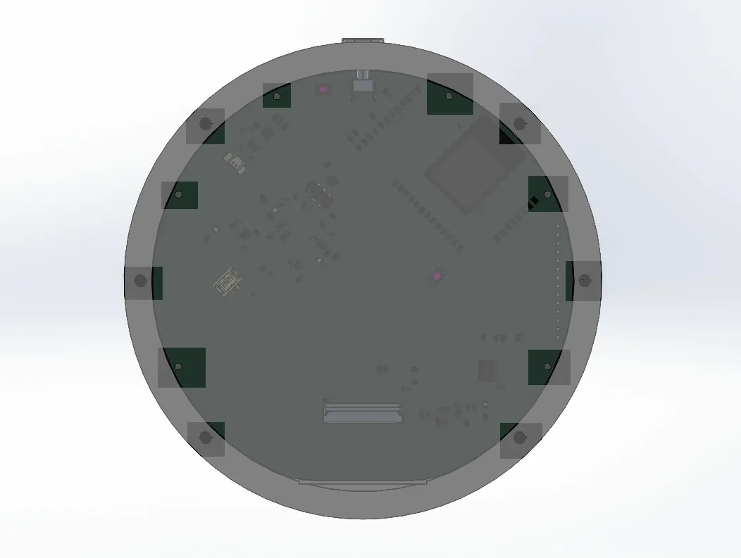
One of the sizes was M1 which were surprisingly expensive to source from the usually suspects. I ultimately found some on Amazon.
Speaker
The speakers I’m using thankfully ship with adhesive foam. I cut a small nest about ~0.25 mm bigger than the speaker in the enclosure’s back as a mounting location. Hopefully the adhesive is enough to keep it into place. Add some holes so the sound escapes and mechanical design is done!
Electronics Design
Schematic Capture
Adafruit did most of the work. “My” design is a mashup up of the Qualia board, MAX98357 breakout, and the charging circuit from the Adafruit Feather ESP32-S3 .
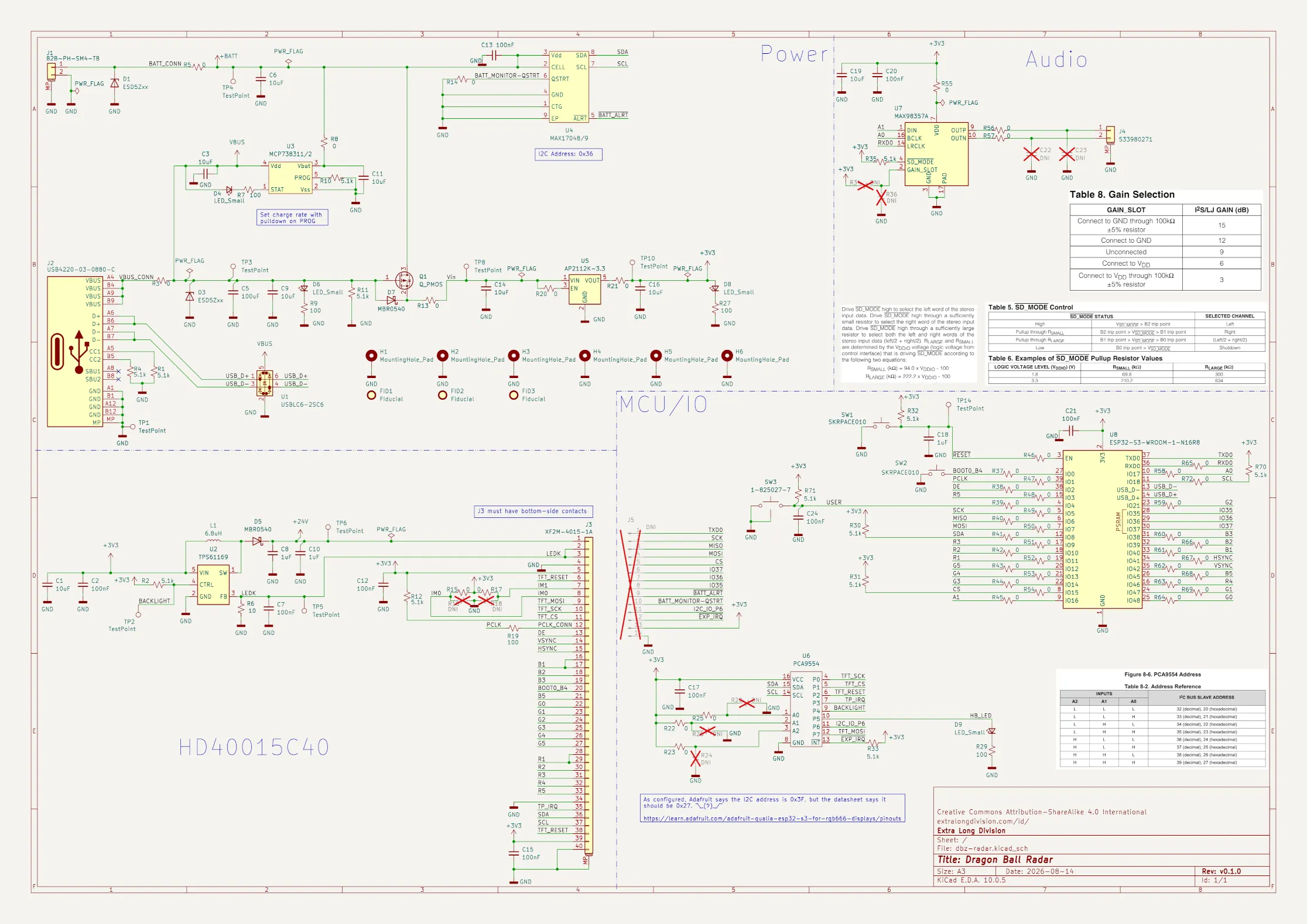
The few modifications I made were:
- Remove the
DNandUPbuttons and replaced them with the button chosen in the mechanical enclosure section - Remove the STEMMA QT/Qwiic connector
- Replace the JST connector with 2.54" spaced THTs and connected all unused IO5 to it
- Add a heartbeat LED6
- Replaced jumpers with 0 ohm resistors, depopulating the ones I don’t want
- Various quality of life changes like adding more test points and egregious amount of 0 ohm resistors in series with interesting traces
PCB Layout
Placement
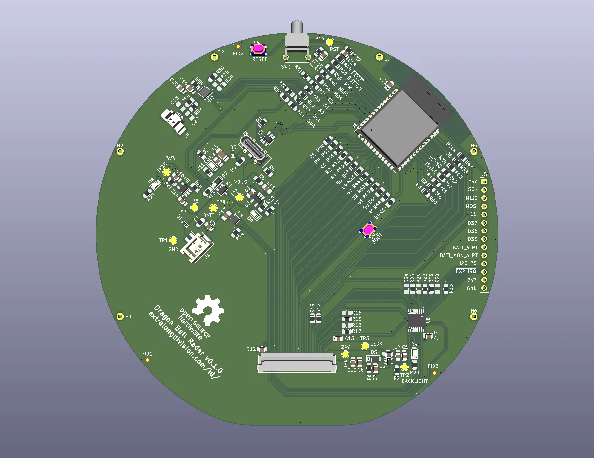
The mechanical design dictated the position of the mounting holes, activation button, and the FFC7 connector (technically I could physically rotate the display and rotate the image in software but I opted just to put the connector and activation button at the vertical symmetrical axis of the device).
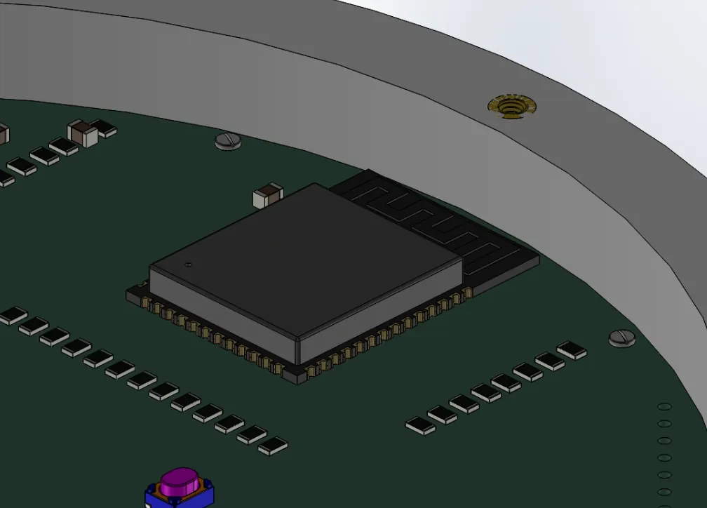
This choice forced me to rotate the ESP32 package 45 degrees to avoid a THT inside a keep-out zone. I put the ESP32 on the top right of the board to give the most amount of space to place other components.
I’m actually still violating the layout rules provided by Espressif. They recommend the antenna hang off the board ideally or, if not possible, the end of the antenna be at least 15 mm away from a cutout and that the feed point be max 2 mm from a board edge.
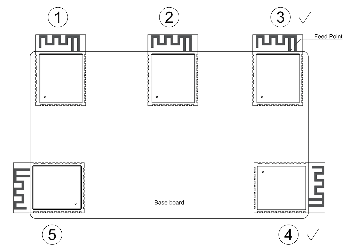
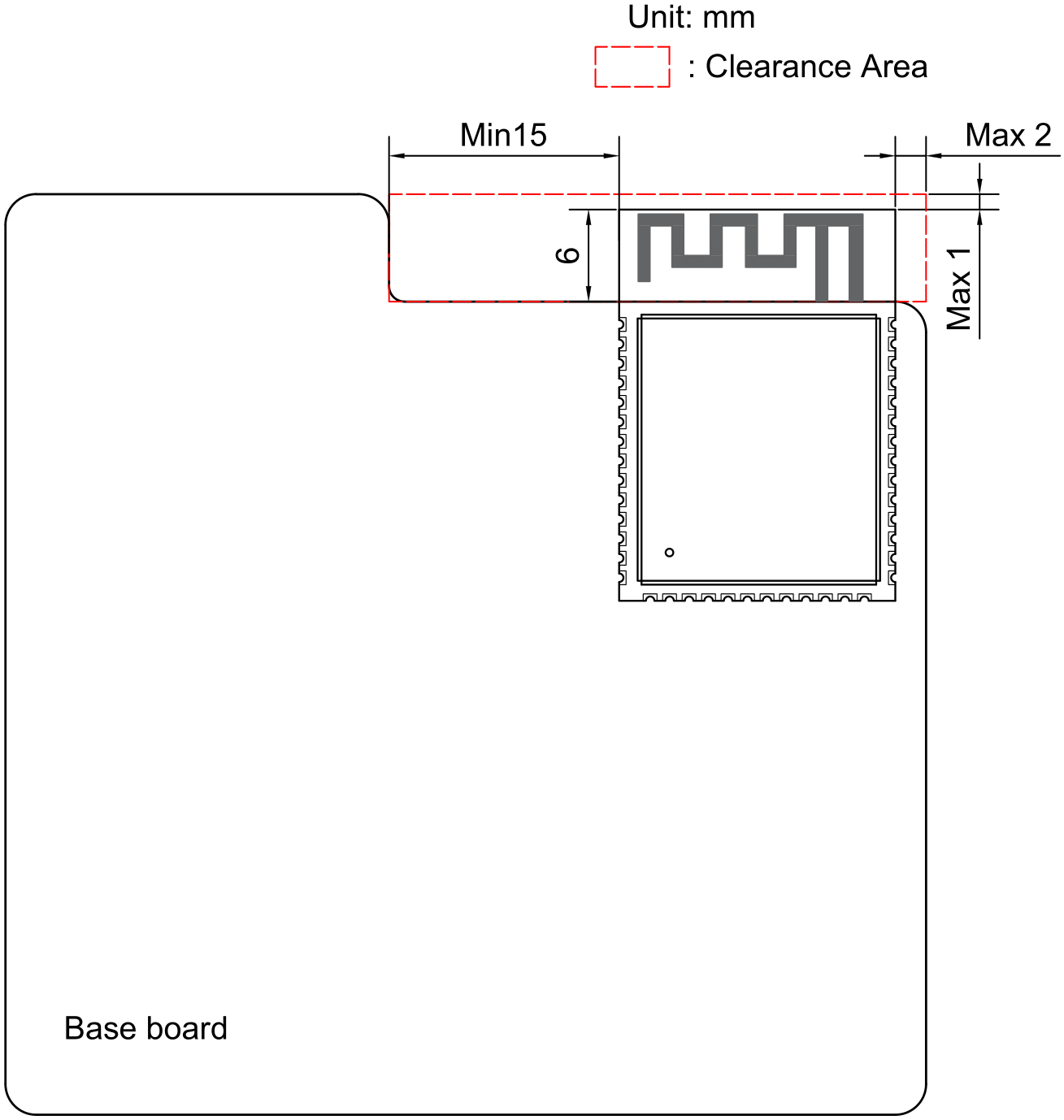
If I hung the antenna off the board it’d collide with the enclosure and I didn’t want to make it any larger.
To make rework and hand-soldering easier, I used 0805 sized components wherever I could. This would make my life easier once the boards came back.
Stack-up
I decided to do a 1.6 mm thick (foreshadowing), 4 layer stack-up of signal+ground/ground/ground/signal+ground. The RGB5658 parallel signals were my greatest concern. The two inner ground layers would shield signals on layer 4 from the RGB. Layer 1 would have the USB9 2.0 traces which technically should be fabricated to 90 ohm, but in practice I’ve never had problems omitting a controlled impedance. I still routed the signals differential though. The four layer stack-up also made it much easier to route 3.3 V power rail on layer 4.
Routing
The most interesting part to route was the USB-C connector. It has a keep-out zone near the pads that make it almost impossible to connect the USB D+/D- pins and VBUS10 pins together.
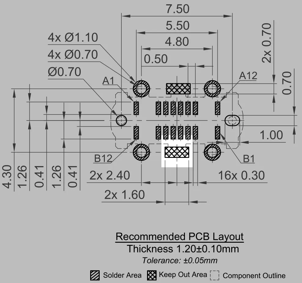
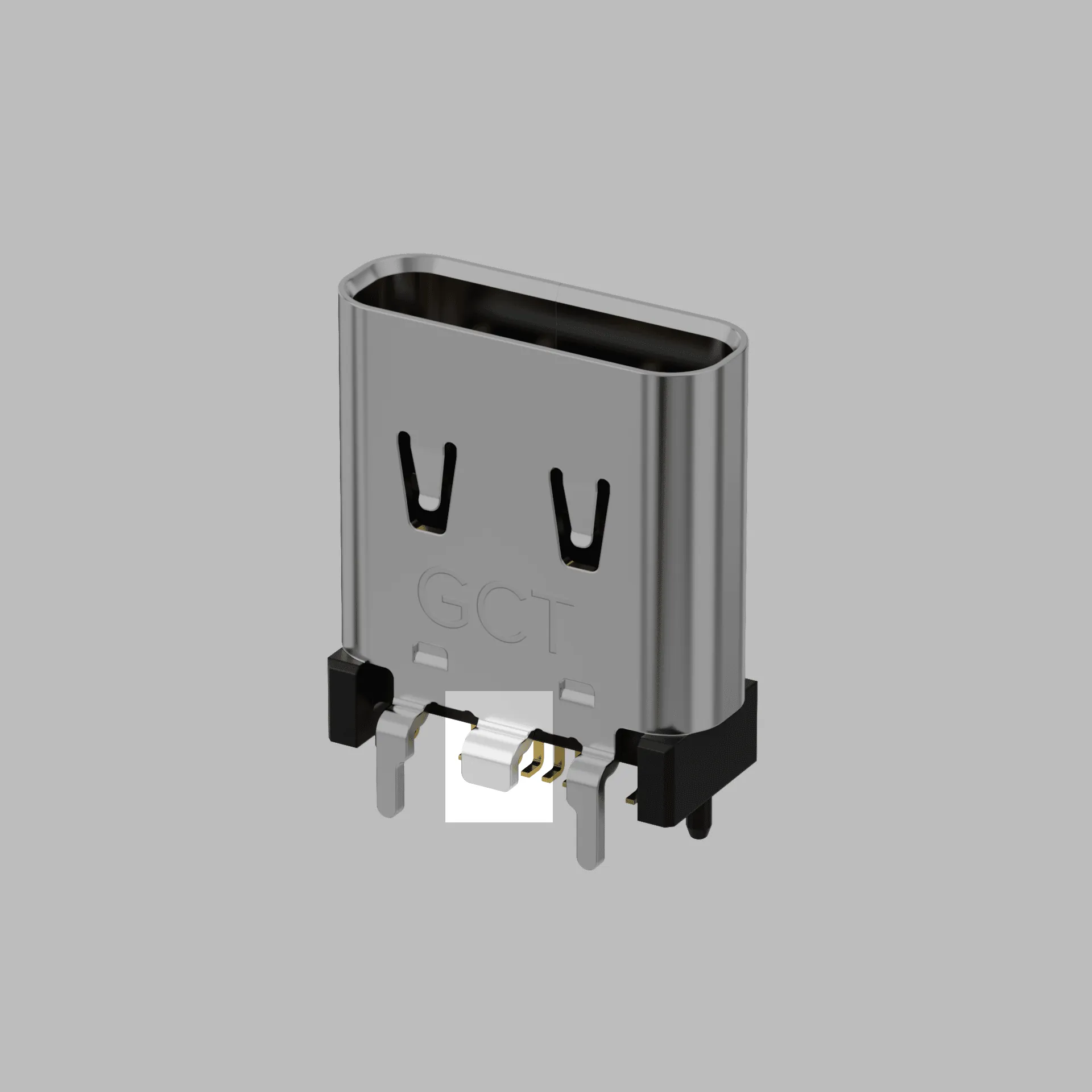
I interpreted the keep-out zone as only for components and not for all copper. I’m justifying this conclusion with the metal flaps on the side of the connector (these will rear their ugly head once the board is made).
Everything else was fairly straight forward to route.
Ordering
While ordering the board, I realized that I assigned a 100 uF decoupling capacitor for the ESP32 instead of a 100 nF cap. If you hadn’t caught on to the trend, I am lazy. I didn’t want to regenerate the gerbers so I just DNP11’d the cap.
The USB-C connector was also out-of-stock. I already designed the mechanical enclosure around that connectors height and (re: lazy) DNP’d that part thinking I could hand solder it on once the boards arrive. That was not a safe assumption.
Board Bring-Up
Physical Inspection
Once the boards came back, I realized just how large they are.
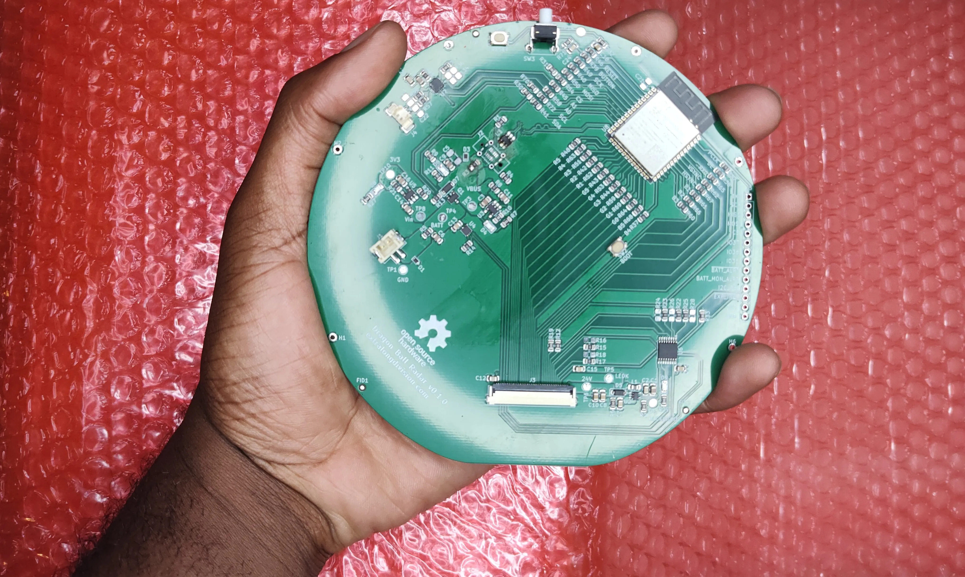
The PCBAs12 are about as large as they can comfortably fit in my hand and that’s before they’re put in a larger assembly. I’ll certainly have to use a wrist strap for the final build.
Smoke Test
I plugged in a battery into the board and… smoke. Quickly, I realized my mistake. I swapped the battery connector polarity. The Adafruit designed I based it on used a horizontal connector, while mine is vertical. This shouldn’t matter, but the manufacturer flipped the location of pin 1 on the datasheet.
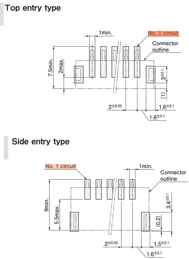
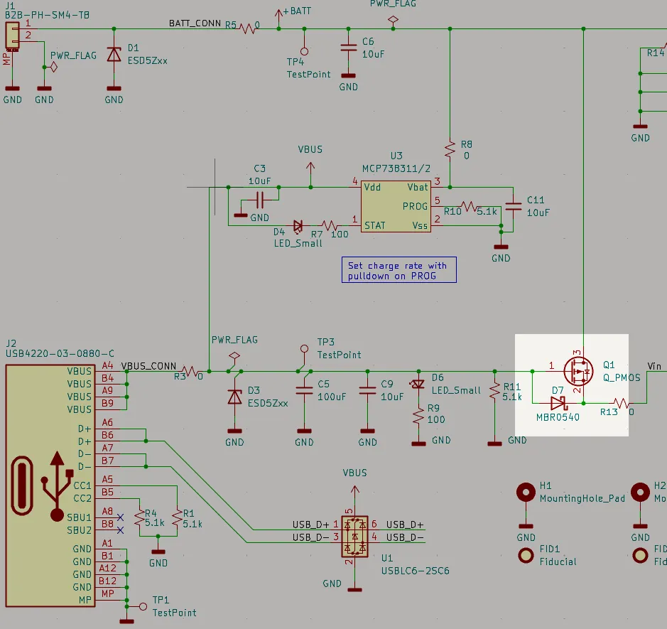
I should’ve caught this, but I will remind JST that pin 1 should be on the top left of a footprint to comply with an IPC13 7351 . Thankfully Q1 and D7 act as reverse polarity protection for the rest of the circuitry.
USB-C
Now comes the most egregious mistake I made in the design that I so un-elegantly foreshadowed earlier. I couldn’t connect a battery so next step was to solder on the USB-C connector.
While earlier I mentioned how surprisingly large the board was. The USB-C pads were surprisingly small.
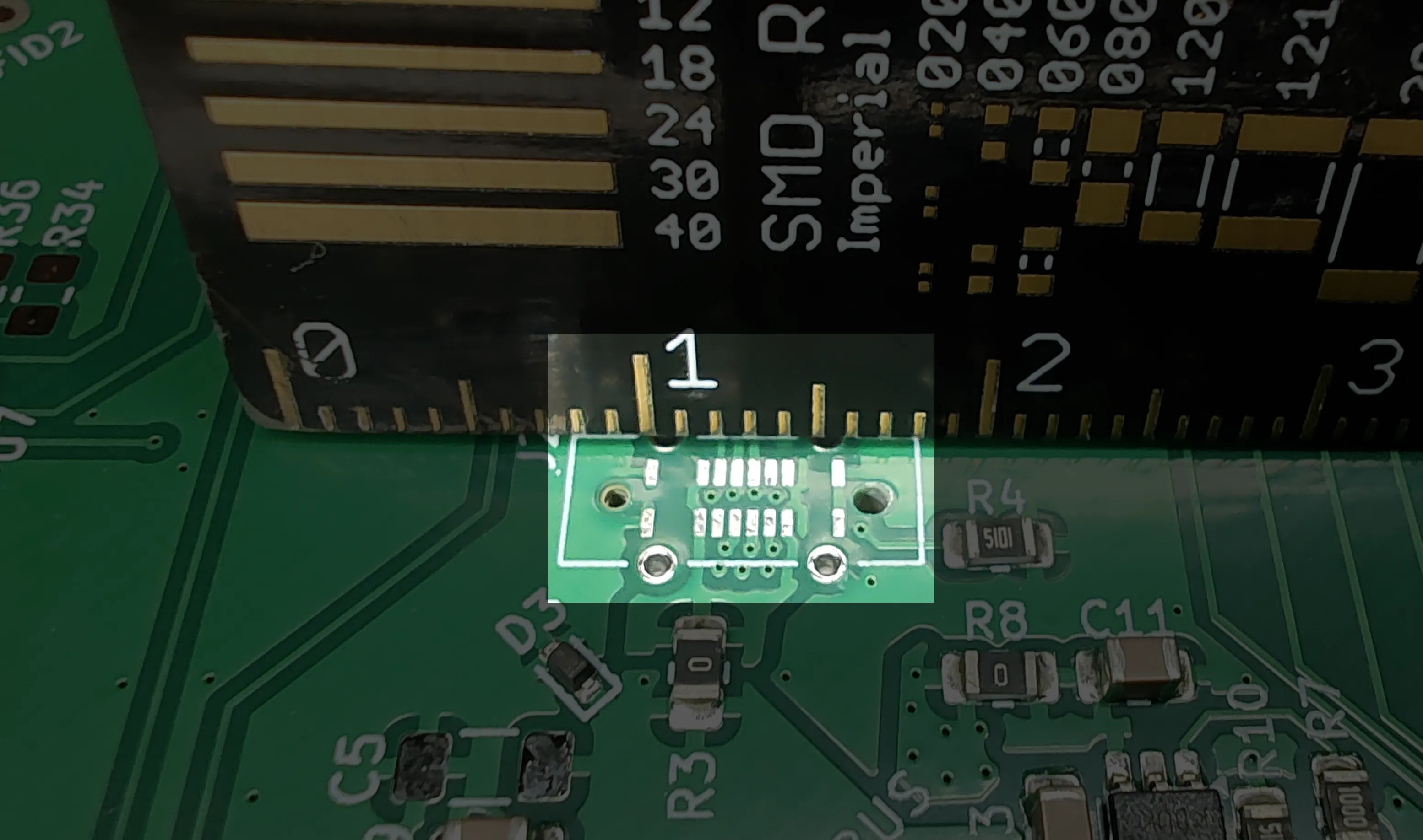
I figured I had my work cutout for me, but then I placed the USB-C connector on the board and spotted another grievous error. The mounting pins for the connector were 1.2 mm long, but the board is 1.6 mm thick.
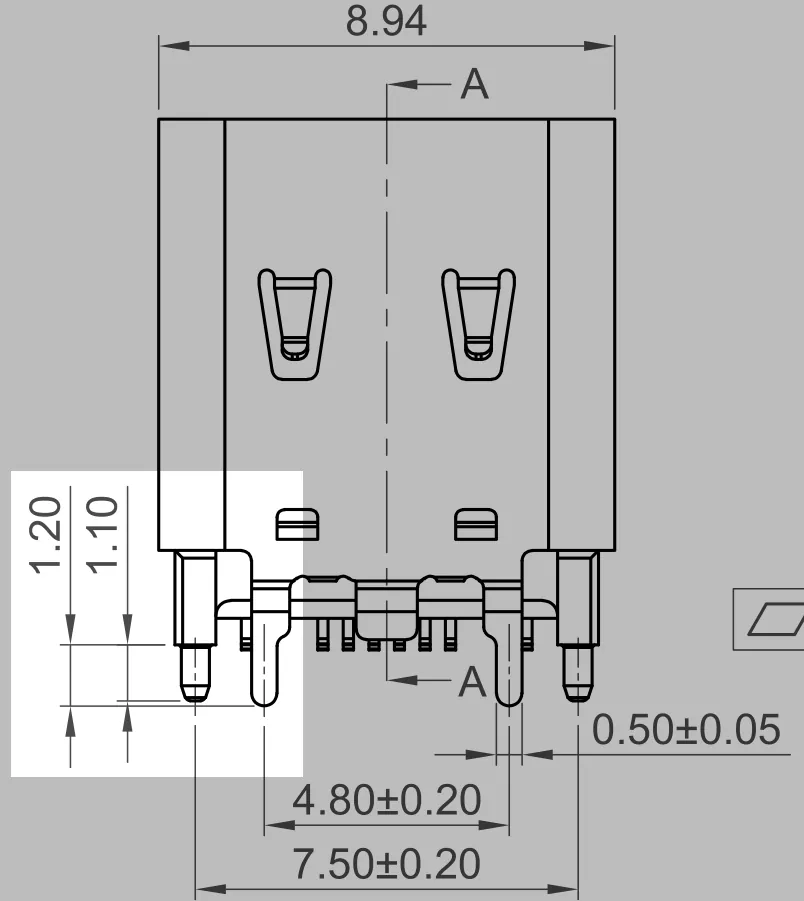
Even if it was in stock, no company on the planet could assemble the connector onto the board. The next revision will have to use a thinner PCB. If you scroll up to the PCB Routing section you’ll notice the footprint has a 1.2 mm PCB thickness recommendation.
But the mistakes didn’t end there. With the connector on the board, the SMT14 pads are inaccessible thanks to those aforementioned side flaps.
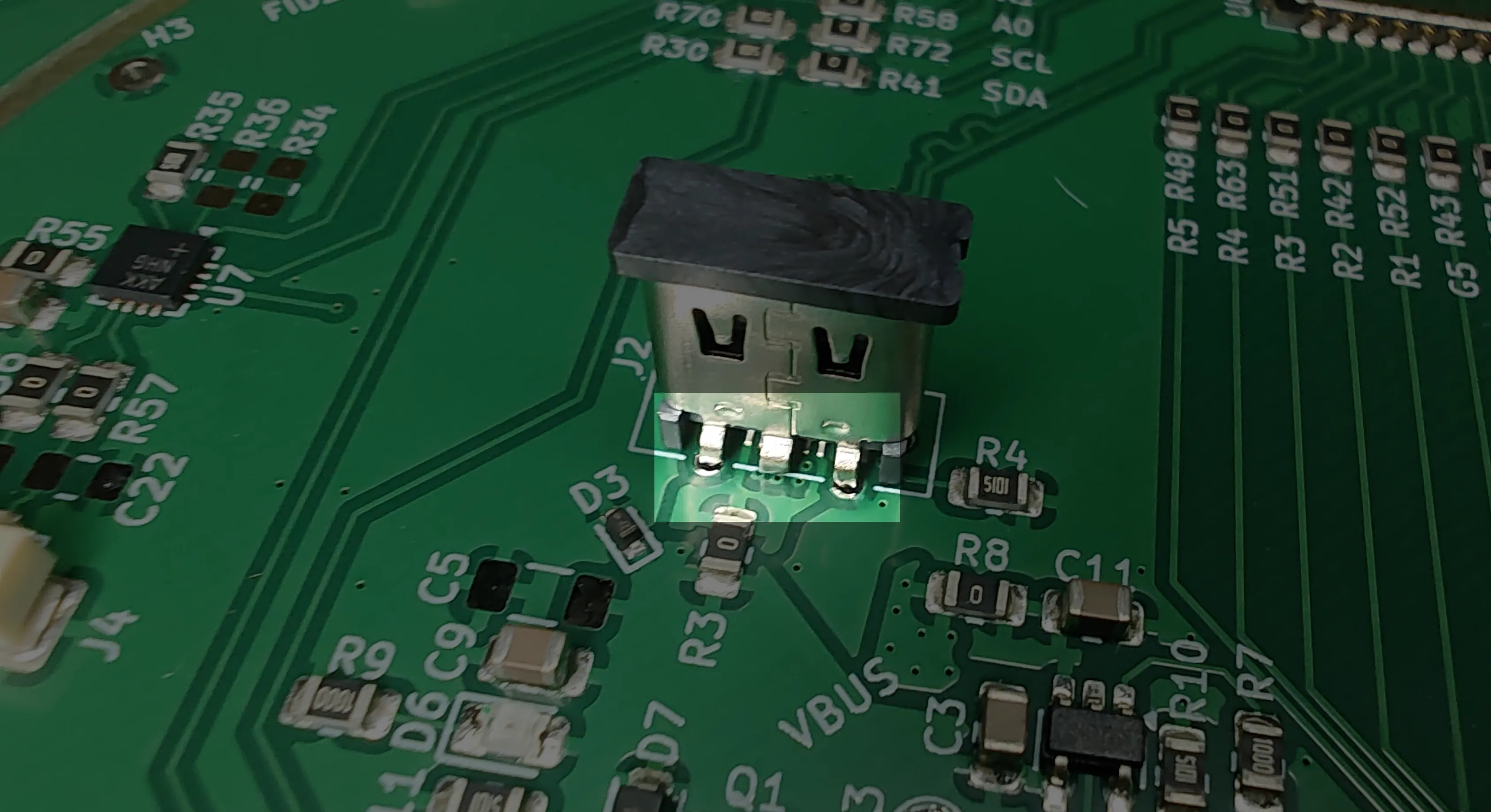
Thankfully, the connector I chose was USB 2.0, not 3.0. With some bodge wires and a spare USB-A plug, I made a haphazard USB cable… which created a short across VBUS and ground. My second attempt worked though. I was able to flash the ESP32 with CircuitPython and upload code to it 😎.
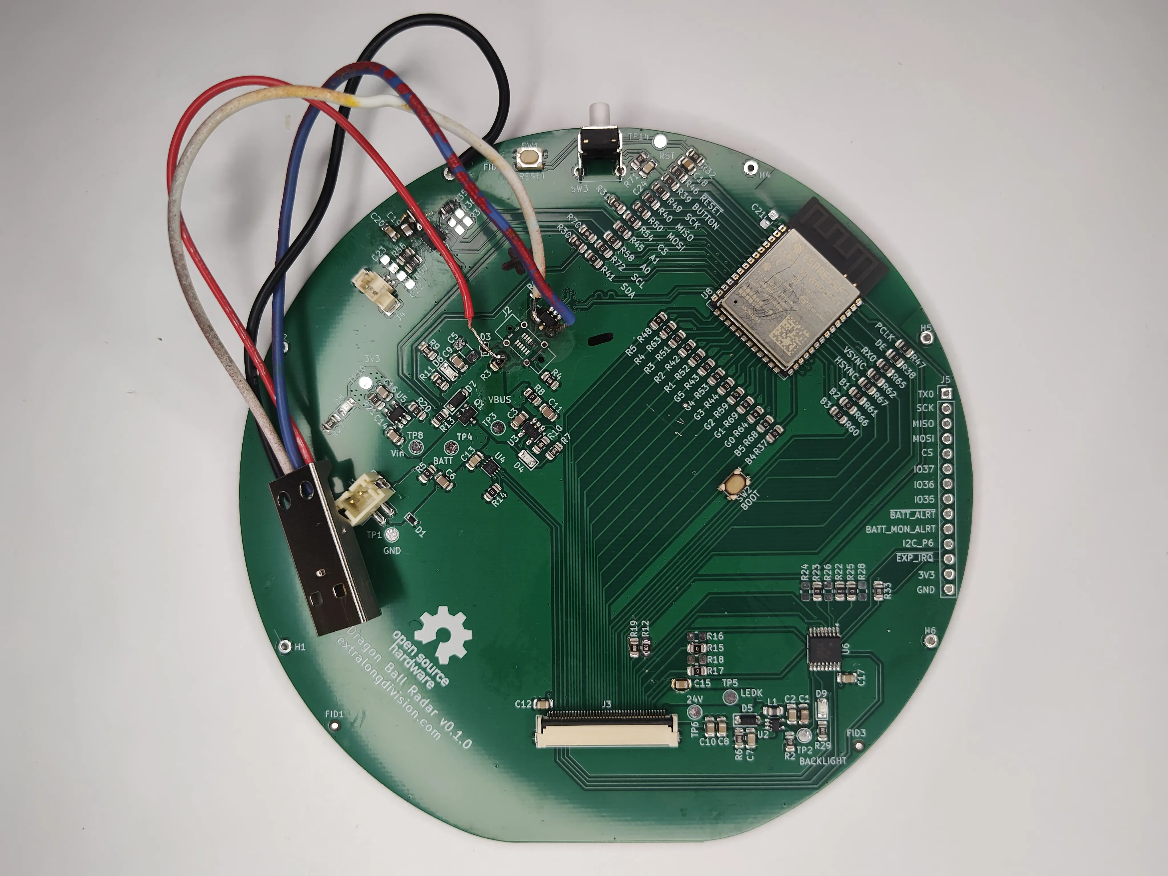
Notice how the D+/D- wires are on the side of ESD15 diode closest to the connector. This ensures that an ESD event doesn’t damage the ESP32.
Also, the process to get CircuitPython on my board was slightly different than the Qualia. This is the tutorial I followed to do it: https://learn.adafruit.com/circuitpython-with-esp32-quick-start/installing-circuitpython .
Battery Charging/Monitoring
I had some faith the battery charger, MCP73831, still functioned because its status LED blinked when the board was on with no battery connected. In the absence of a battery emulator, I connected a lipo16 to the board with some hook-to-DuPont connectors, a 2-pin JST-PH pigtail cable, and the enduring will of the human spirit.
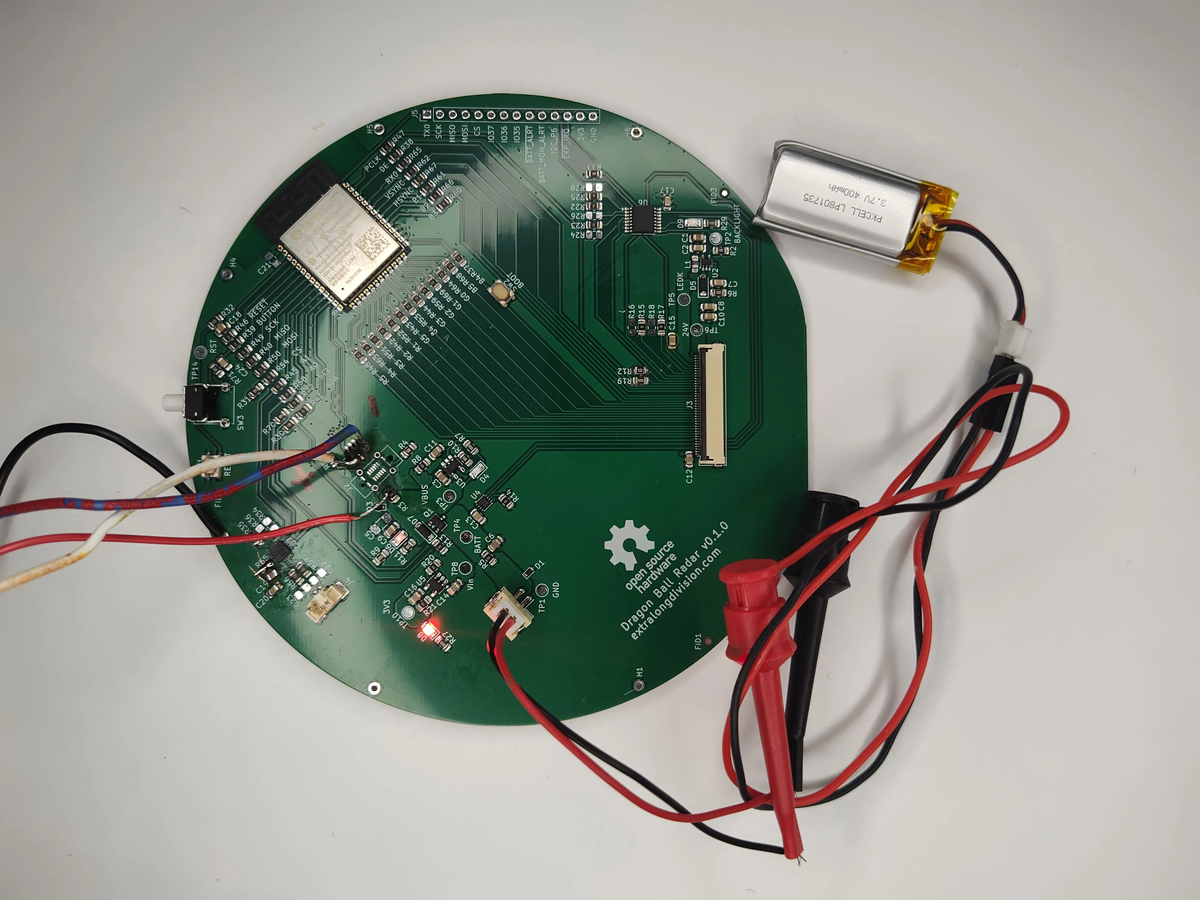
According to the datasheet, the status LED should be on during charging and off otherwise.
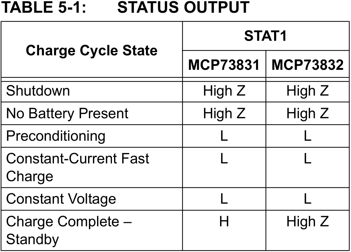
This is exactly what happened. I found a some CircuitPython test code for the battery monitor and easily read the voltage.
# SPDX-FileCopyrightText: Copyright (c) 2022 ladyada for Adafruit Industries
#
# SPDX-License-Identifier: Unlicense

import time
import board
import adafruit_max1704x

i2c = board.I2C()  # uses board.SCL and board.SDA
# i2c = board.STEMMA_I2C()  # For using the built-in STEMMA QT connector on a microcontroller
max17 = adafruit_max1704x.MAX17048(i2c)

print(
    "Found MAX1704x with chip version",
    hex(max17.chip_version),
    "and id",
    hex(max17.chip_id),
)

# Quick starting allows an instant 'auto-calibration' of the battery. However, its a bad idea
# to do this right when the battery is first plugged in or if there's a lot of load on the battery
# so uncomment only if you're sure you want to 'reset' the chips charge calculator.
# print("Quick starting")
# max17.quick_start = True

while True:
    print(f"Battery voltage: {max17.cell_voltage:.2f} Volts")
    print(f"Battery state  : {max17.cell_percent:.1f} %")
    print("")
    time.sleep(1)
I didn’t bother testing how accurate the monitor was as the battery discharged since it’d be hard to track with the USB cable disconnected.
Display
I plugged in a known good 4" display into my PCBA, programmed the board with example code, and… nothing. The display’s back-light turned on which tells me that the pin-out for the connector was correct and that I2C17 works (only partially true, keep reading) since the I2C expander controls the LED driver.
I began to search TTL18 RGB routing guidelines to see if I violated any rules, but I didn’t find anything specific. What ultimately led me to the cause was comparing the waveforms on my board vs the Qualia. All the RGB565 signals looked fine, but when the Qualia booted, its I2C expander (the PCA9554) sent SPI19 signals to the display. There were no SPI signals on my board. The ESP32 produced the expected I2C signals, but the PCA9554 didn’t respond. I realized the problem after doing a port scan.
The example code from Adafruit assumed the I2C address was 0x63while my board configures it to 0x27. I actually left a note about this confusion on my schematic.
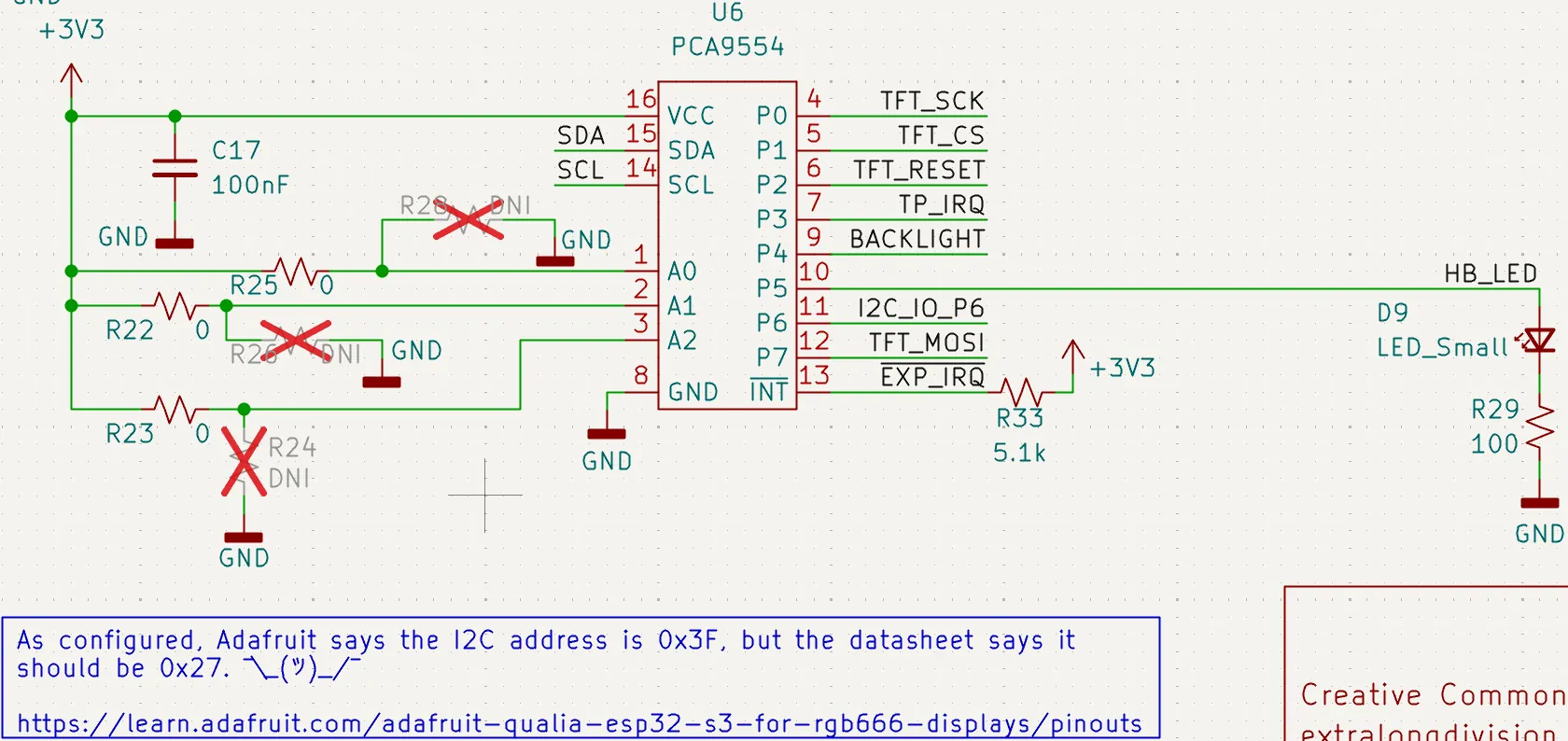
Setting the proper I2C address made the display work properly.
Sound
When I plugged in a speaker and loaded up example code… nothing. Not even the crackling sound I heard during the prototyping phase. I probed the pins of the I2S chip, the MAX98357, and quickly realized the pin assignment for the PCB and the breadboard prototype were different.
For easier routing, I made the following changes from prototype to PCB:
| MAX98357 Pin | Qualia Pin Assignment | Custom Board Assignment |
|---|---|---|
| Bit Clock | board.A1 | board.A0 |
| Left/Right Clock | board.A0 | board.RX |
| Data In | board.TX | board.A1 |
Everything worked after changing the pin assignments in firmware. The sound output was clean too. This makes me confident that the horrendous sound coming out of the prototype was due to bad wiring.
While I’m 99% sure the mismapped pinout was the only problem, before I discovered it, I replaced the pull up resistor on the SD_MODE pin with an 1M ohm one to match Adafruit’s breakout board. I would swap back to the original 5.1k resistor, but I consider the board verified at this point.
Next Steps
-
I have to swap the polarity of the battery connector.
-
I have to make the board thinner.
That’s it. Not bad for a first revision. At this point, I could try to assemble the display and PCB into the enclosure, but it’d be inconvenient to have to disassemble the entire project just to charge the battery. I’ll sort out mechanical assembly once the new PCB comes in.
The repository for this project, though completely undocumented as of writing this, is hosted on Codeberg. . I’ll post another write up here when it’s ready. Subscribe to my RSS feed to get the update as soon as it drops.

Extra Long Division is a maker of questionably functional things and haver of equally questionable opinions. Subscribe to my RSS feed if you liked what you read.

-
developer ↩︎
-
inter-integrated circuit sound ↩︎
-
printed circuit board ↩︎
-
through hole technology ↩︎
-
input/output ↩︎
-
light emitting diode ↩︎
-
flat flex cable ↩︎
-
red, blue, green 5 bit, 6 bit, 5 bit ↩︎
-
Universal serial bus ↩︎
-
voltage bus ↩︎
-
do not populate ↩︎
-
printed circuit board assembly ↩︎
-
previously known as Institute of Printed Circuits, but known known as Global Electronics Association ↩︎
-
surface mount technology ↩︎
-
electrostatic discharge or “static shock” ↩︎
-
lithium polymer battery ↩︎
-
inter-integrated circuit ↩︎
-
transistor-transistor logic ↩︎
-
serial peripheral interface ↩︎